Introduction
As part of the foundations of a Networking career, this post is about learning networking fundamentals. The focus will be on Network interfaces and cables. What are they, the types of network interfaces and cables, how to connect cables, the Ethernet and cable standards, Network Protocols, and the types of connections? Crossover cable and Straight through cables.
Also, When do you use one cable type as opposed to the other? You will learn about some fundamental network cabling concepts like Auto MDI-X and their implication in modern networks.
It will also explore fiber-optics connections, Single-Mode, and Multi-Modes, describe the different modes, and compare them with the copper cables, the advantages of fiber optics, and the drawbacks.
1. What are interfaces and Cables?
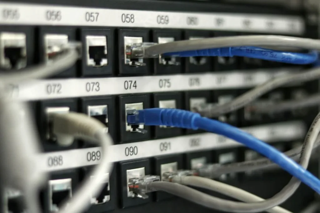
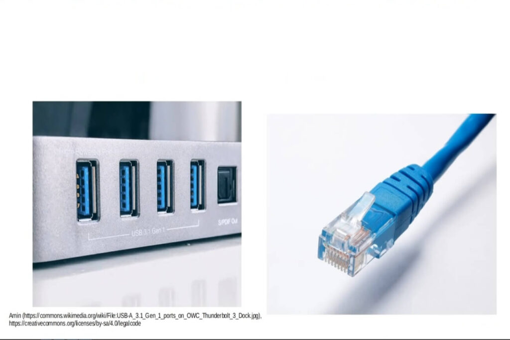
Network Interfaces are ports on a networking device that you plug your cables into, to connect them to other devices in the network. They come in various forms depending on the type of connection or the cable you are using to connect the networking devices.
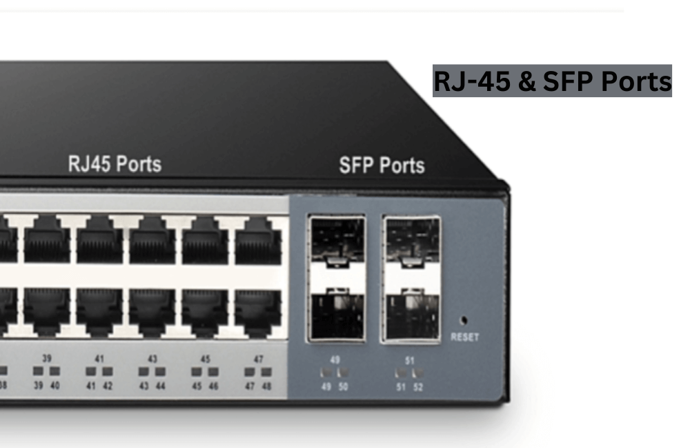
The figure below is typical of switches. It shows several ports for connecting networking devices. Switches have many interfaces to aggregate connections in a network.
1.1 RJ-45 Ports
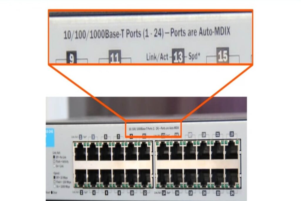
In the figure above, the Ports or interfaces labeled 1-24 are RJ-45 ports and you will usually connect to them using cables that have RJ-45 connectors attached to their ends. The ports are typically used for Ethernet connections. Most networking devices will have this type of port.
The ports are designated as 10/100/1000BASE-T ports and this represents the speed that the ports can support. The Auto MDI-X is a feature that means that the port automatically adjusts to either accept a straight-through or cross-over cable type (concepts that we will describe in detail soon).
A figure of an RJ-45 connector or head is in the picture below
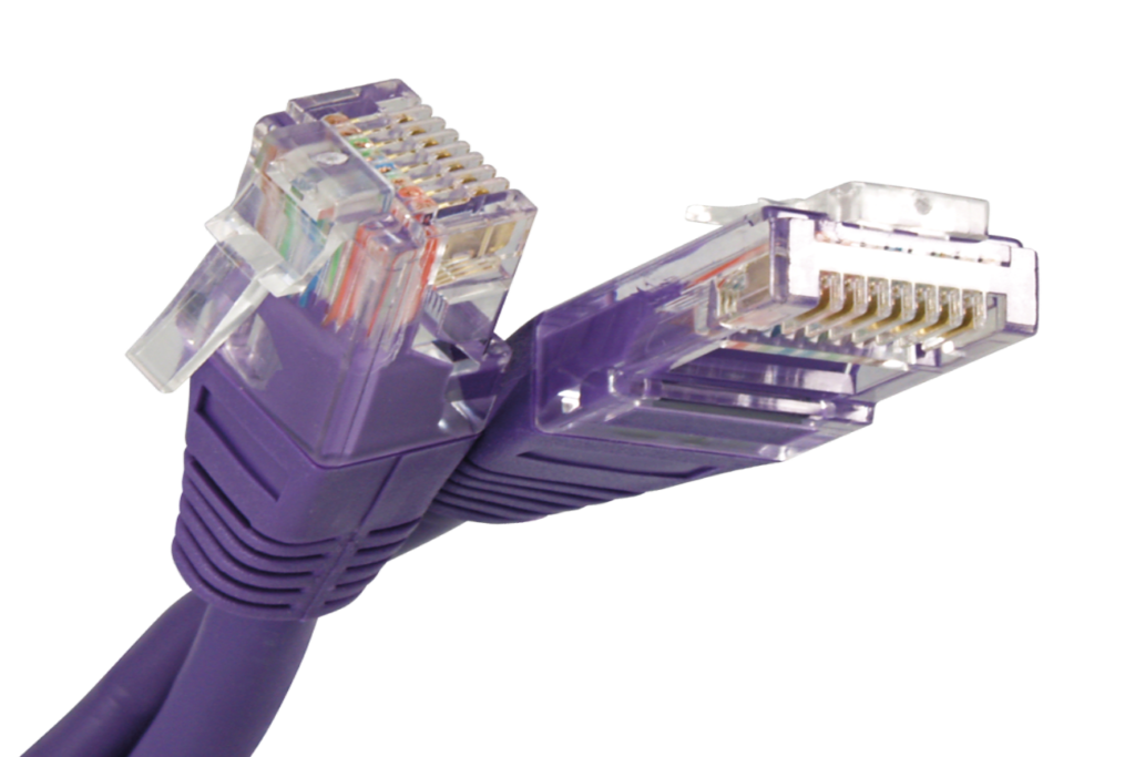
RJ-45 Connector head with a cable attached
The ports that are most common on a Switch are the RJ-45 Ports (Registered Jack 45) which are for Ethernet connections.
Copper ethernet cables are attached to connectors such as the RJ-45 above. Network cables are the physical medium that carries signals in the form of electrical signals from one port or device to another.
Besides the RJ-45 ports, other types of Ports or interfaces perform similar functions. For example, the different ports on a Router are in the figure below;
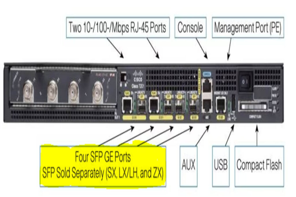
The figure shows 2 RJ-45 Ethernet ports, console ports that are used for the initial configuration of the device, and 4 SFP ports for Fiber Optics connections. Other types of ports shown are the AUX and the USB port.
2. Ethernet
Ethernet is a collection of network protocols and standards, rather than just a single protocol. It was standardized by the Institute of Electrical and Electronics Engineers IEEE in 1983. A protocol is a set of rules that govern how things function. In networking, there are various protocols or standards for various things.
We will focus on the Ethernet protocols or standards for cables. This sets out the standards for describing the different types of cables you can have.
2.1 Why Do We Need Network Standards and Protocols
Network Standards and Protocols ensure that there is a uniform set of rules to govern how things function. This is important as networking devices may be made by different vendors, if there are no Standards or protocols, it will be difficult for those devices (from different vendors) to “talk” to each other.
For example, if you buy a new Switch from Cisco to connect to a network that predominantly has Juniper switches, you are not going to need a new set of cabling types that are specifically designed for the Cisco switch.
Standards and Protocols will make it possible for you to connect the two switches even if they were made by different vendors or manufacturers. There are industry standards all vendors must follow both in terms of physical standards like connectors, interfaces, and cables but also logical standards like the internet protocol. The ethernet standards for cables are one of such standards.
There are a lot of Protocols in Networking and they govern different processes that ensure smooth communications between devices, networks, or processes.
2.2 Network Speeds – Bits and Bytes
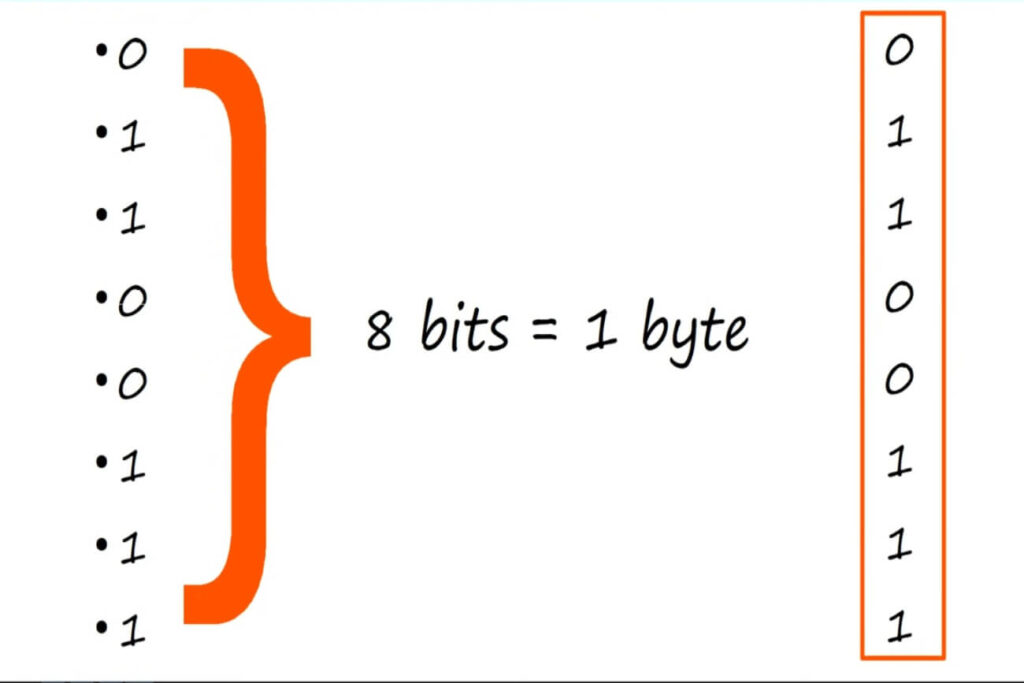
The transmission of data between network devices using the different connection types (wired or wireless) operates at set speeds. These speeds are measured in bits per second (bits/sec). A Bit is a value represented by either a 0 or a 1. This is so because computers only understand binary numbers.
Data is transferred through the medium in the form of tiny electrical currents, in the form of a pulse. A zero bit represents when there is no current and a 1 bit is when a tiny bit of current passes through the medium, forming a binary. These binary bits of 0s and 1s are used to convey different messages based on unique bit patterns.
A Byte is a series of 8 bits. i.e., 8 bits equals 1 byte.
Data traveling through a wire will arrive at the destination 1 bit at a time, so the speed is measured as bits per second. However, data that is stored on a device such as a hard drive or flash drive is stored in Bytes, not bits.
Larger units of speed will be
- Kilobits per second = 1000 bits per second or Kbps
- Megabits per second = 1,000,000 bits per second or Mbps
- Gigabits per second = 1,000,000,000 or Gbps
Most network speeds are from Mbps and Gbps. The same convention is true for bytes i.e. data that is sitting in memory or stored form –
Kilebytes KB, Megabyte MB, Gigabytes GB, etc. (Every letter is capitalized).
- Kilobytes = 1000 bytes KB
- Megabytes = 1,000,000 bytes MB
- Gigabytes = 1,000,000,000 GB
- Terabytes = 1,000,000,000,000 TB
It is worth mentioning that a Byte is 8 times larger than a Bit.
2.3 Ethernet Standard
Ethernet standards are defined by the IEEE 802.3 in 1983. The table below describes some of the Ethernet standards for copper cabling; it includes the speed, common name, the official IEEE standards, Informal name, and maximum length for effective communications.
| SPEED | COMMON NAME | IEEE STANDARD | INFORMAL NAME | MAXIMUM LENGTH |
| 10 Mbps | Ethernet | 802.3i | 10 BASE-T | 100 m |
| 100 Mbps | Fast Ethernet | 802.3u | 100 BASE-T | 100 m |
| 1 Gbps | Gigabit Ethernet | 802.3ab | 1000 BASE -T | 100 m |
| 10 Gbps | 10 Gig Ethernet | 802.3an | 10GBASE-T | 100 m |
The maximum length for all copper cabling before the signals traveling through them degrade (due to attenuation ) is 100 meters. The “Base” in 10 BASE-T (as well as all the others) stands for baseband signaling, and the “t” represents twisted-pair.
The common names ethernet, fast ethernet, Gigabit ethernet, etc. are what network engineers commonly use in their day-to-day activities.
3. Unshielded Twist Pair (UTP) Cables
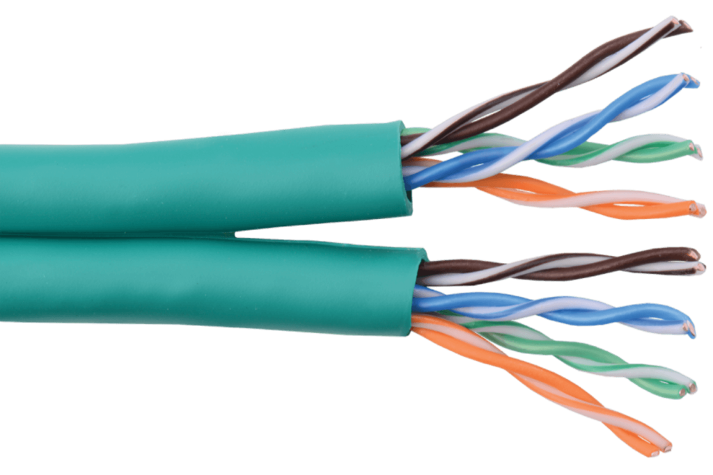
The Copper cables used Ethernet standards are Unshielded Twisted Pair. These are cables that do not have a metallic shield surrounding them (a metallic shield protects against electrical interference). This means that UTP cables are vulnerable to electrical interference. In UTP cabling, the wires are in pairs, with each of them wound or twisted around the other. There are 4 pairs for each complete UTP cable. The twisting helps protect against electromagnetic Interference (EMI).
- UTPs are vulnerable to Electrical Interference become of the absence of a shield
- The Twist helps prevent Electromagnetic Interference or leaks
- The are 4 pairs of twisted copper wires for each cable or 8 wires
The common practice is to attach a UTP cable to an RJ-45 connector or head. Below is a diagram of an RJ-45 connector head up close.
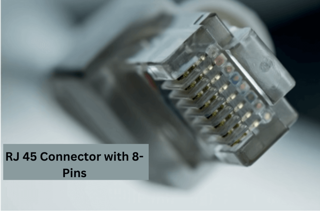
Notice that it has 8 pins, each of which connects to each wire of the UTP cable. However, not all the ethernet standards described in the earlier tables use all 8 wires or pins.
10BASE-T and 100BASE-T (or Ethernet and Fast Ethernet) use only 2 pairs(4 wires) from the 4 pairs of wires while 1000BASE-T and 10GBASE-T (aka Gigabit Ethernet and 10 Gigabit Ethernet) use all 4 pairs of wires (8 wires).
- Ethernet and FastEthernet = 2 pairs of wires (4 wires) for UTP
- Gigabit Ethernet and 10 Gigabit Ethernet = All 4 pairs of wire (8 wires)
3.1 UTP Cables -Ethernet and FastEthernet Cables (10BASE-T and 100BASE-T)
The Ethernet and FastEthernet UTP cables only use 2 pairs of wires. These cables have speeds of 10 Mbps and 100 Mbps respectively. In a Network, a PC or Server usually connects to a Switch and a Switch usually connects to a Router.
3.1.1A PC and a Switch Connection
We will consider the connection between a PC and a Switch in the diagram below;
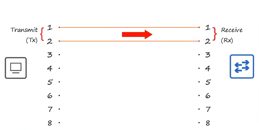
PCs transmit data with Pins 1 and 2, and Switches receive data with Pins 1 and 2
The pins are numbered 1 – 8 for both devices. The first pairs (on the left) are at Pins 1 and 2 on the PC interface. These connect directly to Pin 1 and Pin 2 on the switch interface on the right.
The PC will use Pins 1 and Pin 2 to transmit data to the Switch. We indicate this as Tx on the left. The switch will receive this data on its interface (Pins 1 and 2), we indicate this as Rx (on the right). The switch cannot simultaneously receive
An important point to note here is that the Network Interface Card (NIC) on a PC or a Server uses Pins 1 and 2 to Transmit data. On the other hand, the Network Interface Card on a Switch uses Pins 1 and 2 to Receive data.
The other Pin pair that are used in Transmitting/Receiving data are Pins 3 and 6 (NOT 3 and 4). The reverse process is now operational. The Switch Transmit data using Pins 3 and 6, while the PC Receives Data on Pins 3 and 6 as shown in the diagram below;
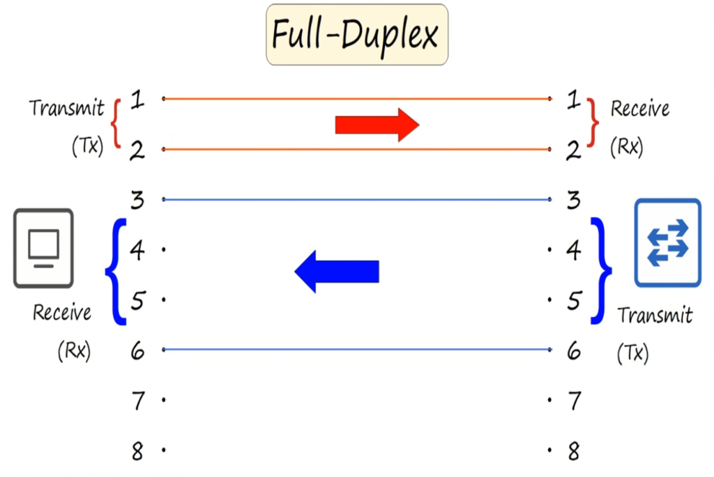
This mode of transmission where both devices can send and receive data at the same time without collision is called a Full-Duplex Transmission. There are no collision problems in Full duplex mode because the two devices use separate wires to send and receive data.
3.1.2 A Router and a Switch Connection
It is common to connect Switches to a Router in a Network, the Data transmission between the two devices is in the diagram below.
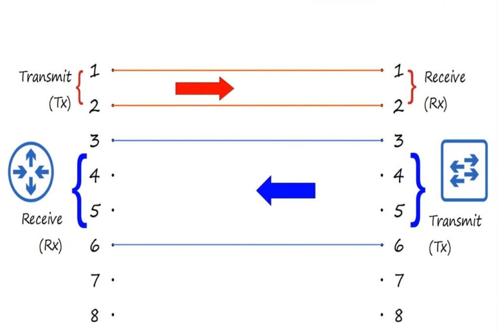
As earlier mentioned, a Switch (on the right) receives data on Pins 1 and 2 and transmits data on Pins 3 and 6. The Router (on the left) transmits data (Tx) on Pins 1 and 2 and Receives (Rx) Data on Pins 3 and 6. Since both devices can simultaneously transmit and receive data without collision, this is also a Full-duplex mode of transmission.
Summary
Below is a summary of Networking Devices and the Pins they use in Transmitting or Receiving Data through Ethernet UTP
| Device Type | Transmit (Tx) Pins | Receive (Rx) Pins |
| Router | 1 and 2 | 3 and 6 |
| Firewall | 1 and 2 | 3 and 6 |
| PC | 1 and 2 | 3 and 6 |
| Switch | 3 and 6 | 1 and 2 |
3.2 UTP Cables – Gigabit Ethernet and 10 Gig Ethernet Cables (1000BASE-T and 10GBASE-T)
1000BASE-T and 10GBASE-T use all 8 wires (or 4 pairs) of the twisted pair to communicate data. The Pin pairs that are used are Pins 1 and 2, Pins 3 and 6, Pins 4 and 5, and Pins 7 and 8. This is different from 10BASE-T and 100BASE-T which use 2 pairs.
All four Pins pairs in 100BASE-T and 10GBASE-T are bidirectional. There are no dedicated pin pairs to either transmit data or receive, any of the four Pin pairs can perform either function. This in part, is the reason they can operate at much faster speeds.
| Ethernet Cable | Number of Pins Pairs Used | Data Transmission |
| 10BASE-T and 100BASE-T | 2 (1 and 2, 3 and 6) | Unidirectional |
| 1000BASE-T and 10GBASE-T | 4 (1 and 2,3 and 6, 4 and 5,6 and 7) | Bidirectional |
4. Types of Networking Cables
The most common types of cables for connecting networking devices are
- Straight-Through Cable
- Crossover Cable
- Roll-Over Cabel.
4.1 Straight-Through Cable
A Straight-through cable is a type of ethernet cable (twisted-pair cable) that is used for connecting networking devices that perform dissimilar functions in the network. For example, connecting a Router to a Switch, PC or Server to a Switch, etc.
In a Straight-through cable, the wire on Pin 1 is connected to the wire on Pin 1 on the other side, Pin 2 to Pin 3, 3 to 3,..etc.Straight-through cables are also called Patch cables. It is most commonly used to connect your end devices or workstations to your switches or dissimilar devices.
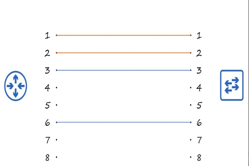
The diagram below shows a pair of wires to Pins 1 and 2, on the Router (on the left) connected to Pins 1 and 2 on the Switch (on the right), also 3 and 6 on the Router connected to 3 and 6 on the Switch.
4.2 Crossover Cables
A Cross-over cable is a type of ethernet cable (twisted-pair cable) that is used for connecting networking devices that perform similar functions in the network. You use Cross-over cables to connect similar devices like two Routers, two switches, 2 PCs, or a PC directly to a Router (since they both transmit the PC and the Router uses the same Pins 1 and 2 to transmit data, 3 and 6 to receive), etc.
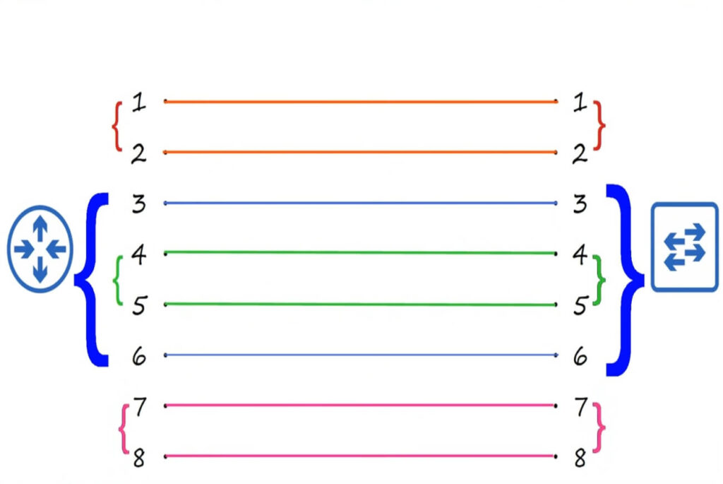
In a Cross-Over cable, the wire attached to Pin 1 on one end is attached to Pin 3 on the other end, Pin 2 on one end to Pin 6 on the other end, 4 to 7, and 5 to 8.
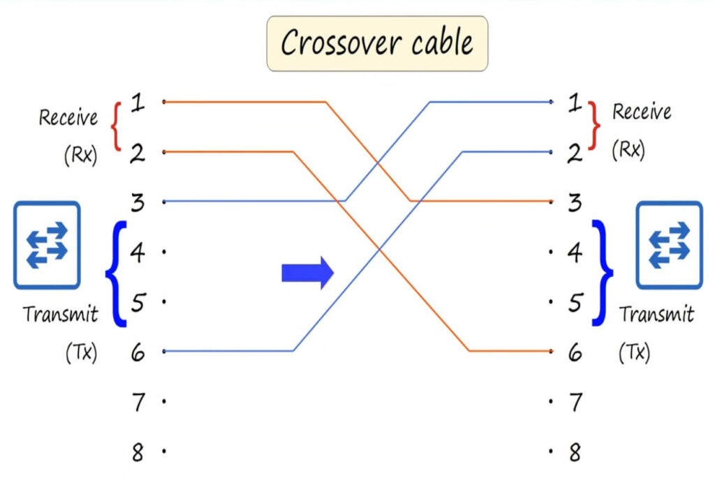
Unlike in a Straight-Through cable, the pairs are in reverse on each end. The wires are crossed over each other. The transmit Pins on one end are connected to the Receive Pins on the other side. See diagram below;

If you directly connect two Routers, two Switches, two PCs, and a Router to a PC using a Straight-Through cable, there will be collisions as these devices use the same Pins to transmit and receive data. A Cross-Over cable is ideal for these types of connections.
4.3 Rollover Cables
Rollover cables are for serial communications, typically, for connecting the serial port of your computer to the console port of a networking device.
They are often used to do the initial configuration of networking devices such as Cisco Routers and Switches, hence they are also called Cisco cables, console cables, or Yost (named after David Yost who proposed the serial cable “standard” for connection for devices). In such instances, Ethernet is not the primary connection. A Rollover cable allows you to make an Out-of-band connection to the device through its console port. (Out-of-band connections do not require IP or Ethernet)
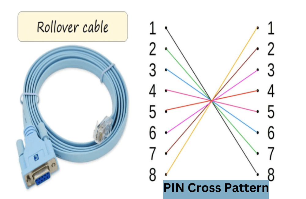
A Rollover cable uses a unique type of crossover connection, it connects or “rollover” Pin 1 on one end to Pin 8 on the other, 2 to 7, 3 to 6, 4 to 5, etc.
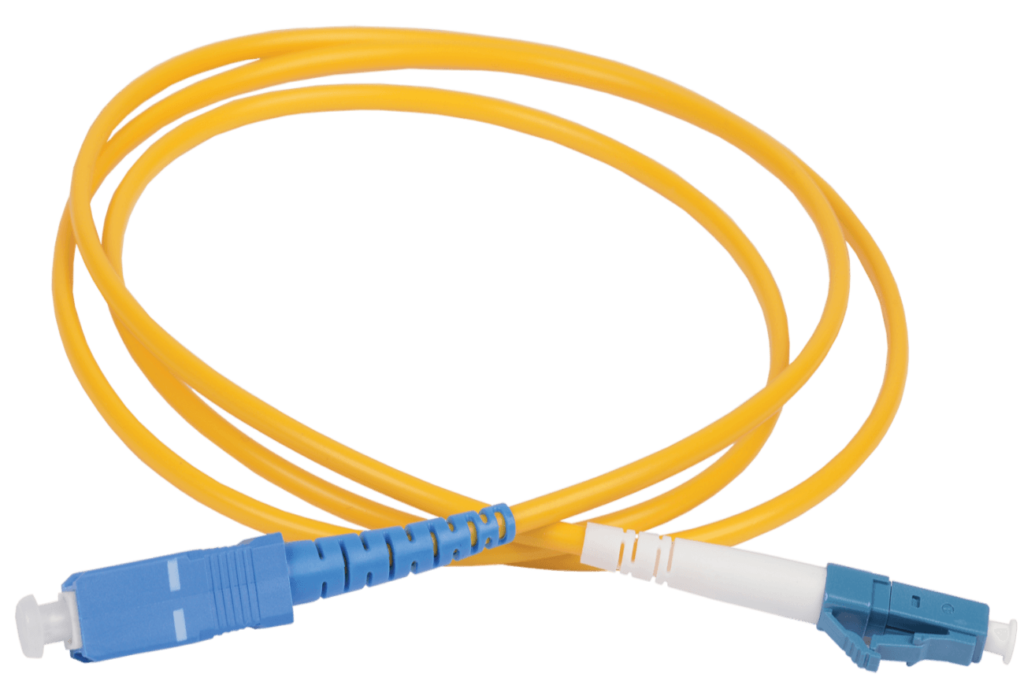
It is typical for Rollover cables to have a DB 9 or an RJ-45 connector at one end for connecting to the terminal of your computer and an RJ-45 or USB head at the other end.
After connecting devices using a Rollover cable, you will require a Terminal emulator to access the terminal of the device to configure it. The most common Terminal Emulator is Putty
5.0 Auto MDI-X
Auto MDI-X (Automatic Medium-Dependent Interface Crossover) is a feature in most modern networking devices that allows them to automatically detect and configure the appropriate Crossover or Straight-through configuration for the connected cables.
If you have devices that are Auto MDI-X enabled in your network, you do not have to worry about whether to use a Crossover or Straight-through cables. Either of the cable types will work fine as Auto MDI-X will automatically detect which Pins their neighboring device is using to transmit data and then adjust which Pins they will use to transmit or receive data.
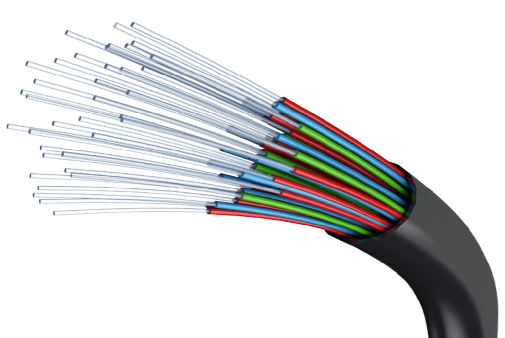
6. Fiber-Optics Connections
Fiber-optics connections send data in the form of light beams through glass or plastic fibers. These fibers are very thin and the beam of light that travels through them is in a pulses. This is similar to how electrical current travels through copper ethernet cables.
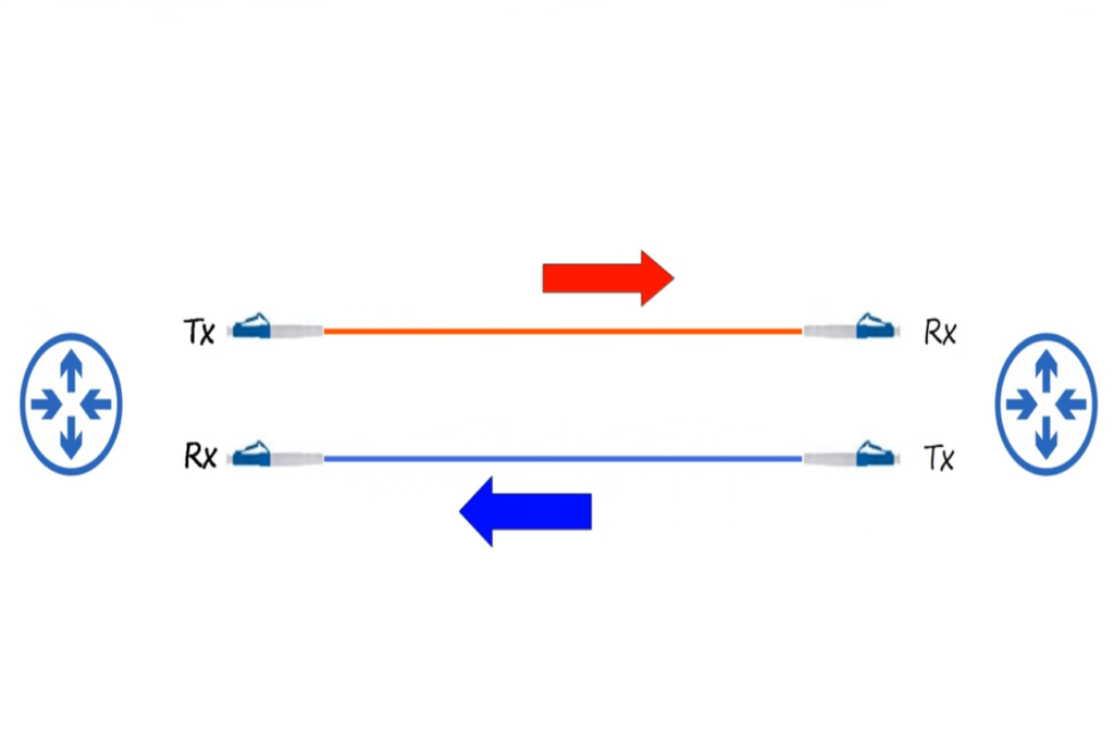
Fiber-optics connections are usually in pairs with two separate connector heads. It uses a separate wire from the pair for transmitting and receiving data. One end has a transmitting head that corresponds to a Receive end at the opposite site and vice-versa
The ends of Fiber-optics cables are into special devices called SFP Transceivers (small form-factor pluggable). It is the SFP Transceivers you plug into your networking device interface(much in the same way you use RJ-45 for copper UTP). Networking devices (Routers) that support Fiber-optics connections will have special ports on their interface for plugging Transceivers.
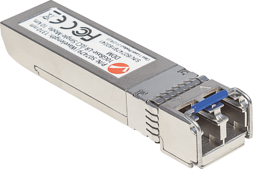
SFP Transceiver for Fiber-Optics connection
SFP Transceivers are plugged into ports such as those shown below;
Fiber-optics connections are much more efficient than copper UTP cables. Unlike copper cables which can only transmit data over an effective distance of 100 meters, Fiber-optics connection can transmit data at longer distances, even up to 30 km without signal degradation. They also support higher speeds/bandwidth, usually Gigabits connections, much higher than you will typically find with copper cables. They are usually employed in an environment where high data throughput is needed.
6.1 Structure of Fiber-Optics Cables
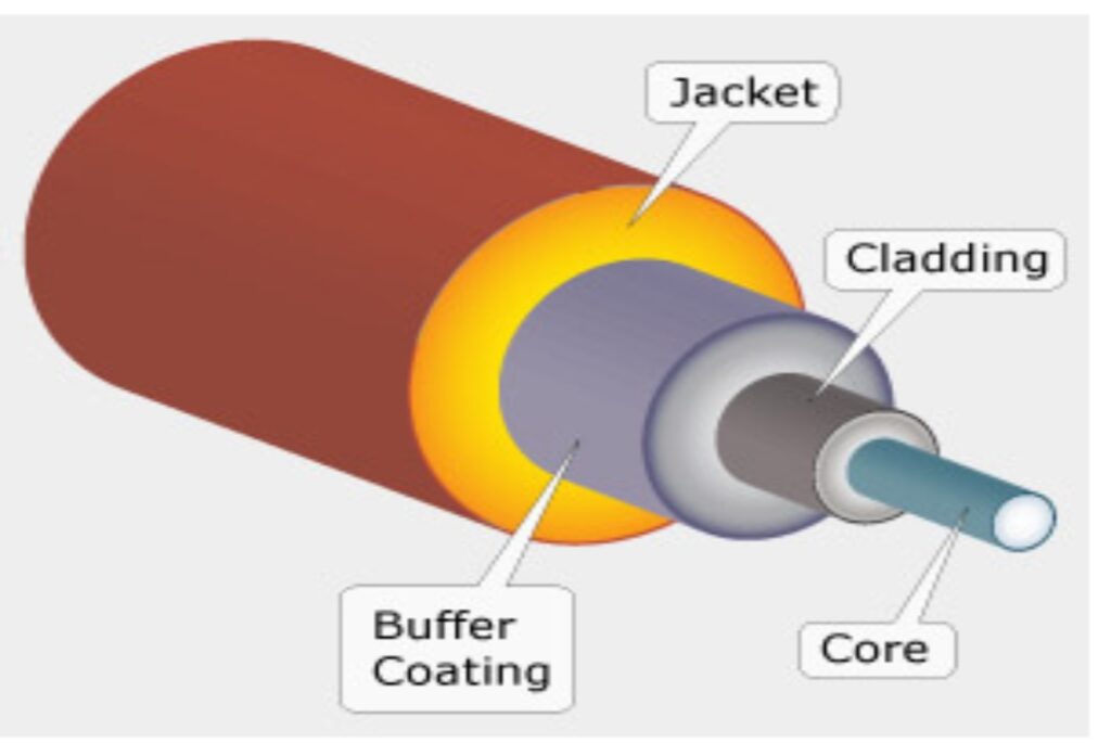
There are four distinct sections in a fiber optics cable, these are;
- A Fiberglass core through which light, pulsating, carries data from one port to another.
- Cladding which reflects light travelling through the fiberglass core.
- A protective buffer that protects the internal fiberglass from physical damage.
- An outer jacket encases the cable and provides an extra layer of protection.
6.2 Types of Fiber Optics
The two types or modes of Fiber optics cable.
- Single Mode Fiber optic cable
- Multimode Fiber optic cable
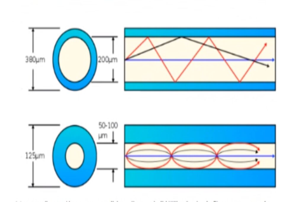
The major difference between the two modes is in their fiberglass core. Multimode fiber optics cable has a wider core (in the above example 50-100 and 200 micrometers) than Single-mode Fiber optics cable. Such a wide core(in multimode) allows for light to enter the glass core at multiple angles or modes. The light signals are reflected off the reflective cladding as it travels through the core. This can reduce the quality of the signal over a very long distance, making them less efficient than Single-mode fiber optics cables.
Multimode fiber optics cable can carry signals over longer distances than a copper wire. They use relatively less expensive LED-based SFP transmitters (compared to single-mode)
In single-mode Fiber optic cable, light enters the glass core at a single angle or mode. They have a thinner glass core (about 10 micrometers in some cases)and there are no reflections off the claddings surrounding the core.
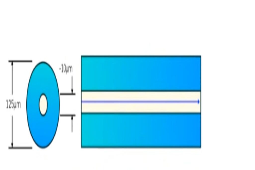
The light travels straight through the core. They use more expensive laser-based transmitters. Single-mode Fiber optics cables can travel longer distances than both multi-mode and copper cables. They are also much more expensive than multimode fiber optics cables.
6.3 Comparison Between Single-Mode Fiber Optics Cable vs Multi-Mode Fiber Optics vs Copper Cable
The table compares the single-mode, multi-mode, and copper cables (twisted-pair)
| Single Mode | Multi-Mode Fiber | Copper Cable | |
| Distance | Longest (up to 30 KM) | Less distance(>than Copper) | Max of 100 m |
| Cost | most expensive | less expensive | least expensive |
| Transmitter | Plasma-Based | LED-Based Transmitters | None |
| Signal | Light | Light | Electrical signal |
| Electro-magnetic Interference (EMI) | vulnerable to EMI or signal leaks | Not vulnerable to EMI or signal leaks | Prone to Electromagnetic Interference |
| Ports | SFP ports(Transceivers) | SFP ports(Transceivers) | RJ-45 ports |
6.3 Fiber Optics Cable Standards
Just as we have cable standards for Ethernet Copper cable standards, there is also a Standard for Fiber Optics cable standards. The table below is a description of the Standards, Common names, IEEE standards, Speed, Cable type, and Maximum length.
| Informal Name | IEEE Standard | Speed | Cable Type | Maximum Length |
| 1000BASE-LX | 802.3z | 1 Gbps | multimode or Single-mode | 550 m (MM) 5 km (SM) |
| 10GBASE-SR | 802.3ae | 10 Gbps | multimode | 400 m |
| 10GBASE-LX | 802.3ae | 10 Gbps | single-mode | 10 km |
| 10GBASE-ER | 802.2ae | 10 Gbps | single-mode | 30 km |
Conclusion
Network Interfaces and Cables describe different ways you can connect networking devices. The 802.3 Ethernet standards for cable specify the types of copper UTP. The connections using copper ethernet cables can either be with Straight-through, or crossover cables depending on the type of device interfaces. Rollover are for out-of-band connections.
Fiber optics connections are much more efficient, they use right rather than electrical signals, are not vulnerable to electromagnetic interference, and can travel much longer distances. They are however much more expensive than copper UTP.
Read TOP NETWORKING DEVICES YOU SHOULD KNOW AS A BEGINNER
Reference: https://www.jeremysitlab.com/
Credit¹: https://www.jeremysitlab.com/